Friday, August 24, 2012

Booting via PXE (Example)


Normally, a computer tech will boot a computer from a USB flash drive, or a CD/DVD-ROM when special utilities are needed. Sometimes the computer seems to block all of the normal options but still must have its data saved. It’s not always easy being a computer tech.

The other day I was given a laptop to work on. I was asked to wipe and reload it with a fresh copy of Windows. I was also told that the computer had a virus and was slow to respond. My initial scans did not reveal a virus but the computer definitely was slow. Perhaps the virus had already been cleaned by another tech but there still appeared to be damage to the operating system. Running MSCONFIG and using it to disable all start-up programs and non-Microsoft services gave it a boost which was enough to make the computer incomplete, but usable.

I needed to back up the data before wiping the computer. The hard drive was 30 gigs with 20 used. I wondered how much of that would be temporary files or files that I would not need to back up so I tried to run SpaceSniffer from my USB flash drive. ( www.uderzo.it/main_products/space_sniffer/ ) The light on the flash drive lit up then went out. It was not recognized by the system. I didn’t even get an error message about it. I tried an external USB hard drive. It spun up but was not able to be recognized either. It seemed that the USB ports were not working. I assumed that the problem was a driver within Windows because the port was still supplying power to the USB port. I was not going to be able to do a sparse file copy backup from within Windows.

I decided that I would boot off of a BartPE live CD and take a hard disk image with DriveImageXML. ( http://www.nu2.nu/pebuilder/) / ( http://www.runtime.org/driveimage-xml.htm ). The hard drive was again not recognized. I tried both USB ports…nothing. The USB ports are either bad or disabled in the BIOS. … I then checked the BIOS and there were no settings for disabling the USB ports. Sooooo…… how am I supposed to backup this data?

I know! I’ll just take the hard drive out of the laptop and hook it up to external reader. Nope, this laptop was one of those types of laptops where you have to take the whole thing apart just to get at anything. Scratch that.

So I took inventory of what works and what doesn’t work. The hard drive works, the CD-ROM drive works, the USB ports DON’T work. What options do I have left for backing up 20-som gigs of data? Burning CDs was out of the question because it would have taken at least 29 CDs. I came up with a sharp idea about repartitioning the hard drive into 2 partitions and then backing up the data from the old partition to the new partition. However, there was too much data on the drive for that to work well without moving some data off of it first. I still needed to find a way of getting that data off the hard drive safely.

I then tried file sharing within Windows but that did not work. Figuring that there was corruption within the operating system I decided that I would need ANOTHER operating system to get at the data and transfer it over the network. PartedMagic can do that and it can help with the repartitioning idea if the network file transfers turn out to be too slow.

No blank CDs. Great time to be out of blank CDs. All I would have to do is burn a PartedMagic CD, boot off of it, and do the partitioning and network file transfers. Why did I have to lend my copy to somebody AND be out of blank CDs? Okay, well, whatever. I’m a computer tech and computer techs solve problems. The solution for the future may be to have more than one copy of PartedMagic. The solution for now would be a bit more technical.

OH BOY! A CHALLENGE! So, how do you boot a computer from a device other than it’s hard drive, a flash drive, or CD? PXE, that’s the answer! Simply put, PXE (Preboot eXecution Environment) is a method of booting computers from a file given to it by another computer on the network. ( http://en.wikipedia.org/wiki/Preboot_Execution_Environment ) Most computers nowadays support PXE, although it is rarely used in home environments. I also have not met many computer techs that have used PXE.

It had been a long time since I myself had used PXE and I made some mistakes this time before I got everything right. Here are some problems I encountered before having a successful PXE boot… before actually doing it RIGHT.

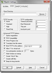
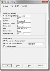
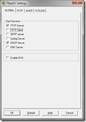
These are screenshots from the settings tabs of TFTPd32. The third picture shows the correct boot file to send to the PXE-enabled computer.

Settings 1  Settings 2  Settings 3

First tried to just pass the bzImage file. Once I managed to get the PXE booting laptop to download the file I got the following error message “NBP is too big to fit into free base memory.” - http://serverfault.com/questions/247445/pxe-boot-nbp-is-too-big-to-fit-into-free-base-memory 

I then read up on PXE to see what I was doing wrong. Turns out that I needed pxelinux to be passed first and then IT would boot the bzImage file. This is like chain-loading. - http://www.syslinux.org/wiki/index.php/Download

I obtained the pxelinux.0 file from the Syslinux package. I then used an example pxelinux.cfg from the PartedMagic website. Error message this time was “Could not find ramdisk image: /pmagic/initramfs”. I mostly copy and pasted the example on the PartedMagic website into my configuration file. However, there was no file named ‘initramfs.”. I then downloaded the specific PXE version of PartedMagic. The ‘initramfs’ file was not there either. - http://partedmagic.com/doku.php?id=pxe

So, where is the file? I looked more closely inside of the PXE version of PartedMagic and found a folder called ‘boot’ which had a file called ‘sample_pxelinux.cfg’. Jackpot! This pxelinux.cfg was different than the one that I found on the Internet at the author’s website. Perhaps that was an old webpage? No matter. The new pxelinux.cfg was different. The line “INITRD pmagic/initrd.img” replaced the line “INITRD pmagic/initramfs”. Well, that makes a world of difference! There actually IS a file named '”initrd.img”. We’re in business now!

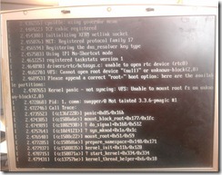
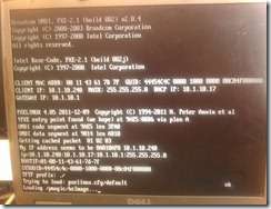
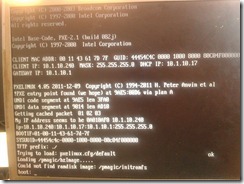
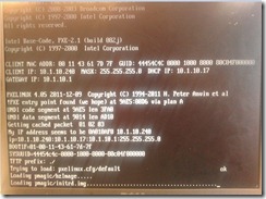
These are some pictures of the PXE boot of the laptop. Each picture shows a different try. The first shows that I set up the PXE boot on TFTPd32 wrong. The second one shows that I configured at least a portion of it correctly with the result of those incorrect settings shown on the third picture. The forth picture is what the good PXE boot looked like.
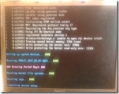
Kernel PanicLoad bzImage

Missing fileLoad initrd


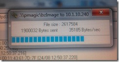
Sending bzImage This is a picture from the TFTPd32 program. So, now I was able to boot the laptop from PXE. Crossin’ my fingers now, hoping that this works considering that seems like it’ll take an hour passing 236,673,901 bytes of data. (EDIT: It took 40 minutes.) This laptop only has 512 megabytes of RAM in it. I don’t need any more bad news, just please let this work.

Loading PartedMagic Everything worked as expected after the boot files were sent! After it booted, the system acted just like as if I had booted PartedMagic from the CD.

I attempted to setup the network connection on the laptop and connect it to a network file share.  Oddly, the laptop was getting assigned the same IP address as my laptop. Weird. Had to reset the router which provided DHCP and then release and renew the IP addresses on both laptops. I used “ipconfig /release | ipconfig /renew “ on my laptop and then “dhcpcd –k eth0” and “dhcpcd eth0” on the customer’s laptop (Parted Magic is a linux live CD) and both computers were online. I was then able to backup the files to a network share.

The rest of the story was a near typical reinstall of Windows. The files that were backed up were returned to the computer via the network again. Add another notch to the I.T. belt.


References / Links:

Configuring TFTPd32 - http://tftpd32.jounin.net/

PXELINUX - http://www.linuxfordevices.com/files/misc/pxe_boot_stb-howto.html 

PartedMagic - http://partedmagic.com/doku.php?id=downloads
Sunday, May 20, 2012

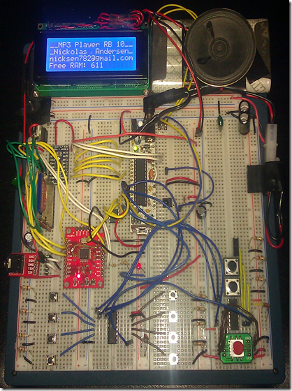
VS1053b-based MP3 Player

Part 1
image
Please note that this will be a multi-part article. This is the first post on this topic and will cover the overview of my learning experience with this project. There will be additional posts in the future dealing with some of the more specific parts.
Usable Features
  • Plays MP3, WAV, WMA and MIDI files
  • Files stored on a 2-gigabyte SD card
  • Song playlist stored as a text file on the SD card
  • Track forward/backward, Play, Pause, Volume up/down buttons
  • MP3 player can be controlled via hardware buttons, IR TV remote, and serial console commands
  • Automatic skip of files that cannot be opened
  • LCD screen displays song data
  • Power-on audio greeting (stored on I2C EEPROM)
  • Parsing of ID3 tags (display via serial console)
  • Shuffle (random play) (poor randomization)


Tuesday, August 2, 2011

Persistence Of Vision (with full color graphics)

This is my Graphical Persistence of Vision display.


It uses 16 RGB LEDs to display full color 24-bit bitmap files created by the MS Paint tool. What is especially cool about this project is that unlike many common POV systems, this one displays full color graphics, not just text.  Above is a Youtube video showing the POV in action.

Initial Designs:
An early design with 8 RGB LEDs and 3 shift registers.
The TV remote was used to change program settings
while the device was spinning on the ceiling fan.
Initially, the POV was created using 8 red LEDs, a shift register and an Arduino.  This allowed for single color text based images.  Once I gained experience and learned the concepts the design moved on to use 8 RGB LEDs.  For this I used 8 common-cathode RGB LEDs, 3 shift registers (parallel out), and an Arduino.  Considering that each LED had 3 available colors in it I needed 3 times the number of I/O lines, which was 24.  By daisy-chaining 3 shift registers I was able to have the 24 I/O lines needed for my LED array.  In this version, each color was assigned a specific shift register.  If I wanted only blue lights then only that shift registers would receive 1's.  If I wanted PURPLE then I would send 1's to the RED and BLUE shift registers.  This allowed me to combine colors as well required complex methods to store color information in the graphics.  I did not have an efficient means at this point to use multiple colors in the same image so I would pretty much would just change the color of an entire image rather than have an image with multiple colors.  Plus, the color palette was limited so I was only able to display text and very simple single color graphics.  Each single-color image required a 36 byte array.

Sample Images of this POV version:


16 Color Bitmaps:
I wanted to develop an easier method of adding color to my images so I started to research bitmaps.  I first tried 16 color bit maps because they were small file size and stored each pixel as a color.  This Arduino code was the first to utilize MS Paint bitmap files and was much simpler than my previous attempts at adding multiple colors to an image.  My code would cycle through each byte in the bitmap, determine what color it represented, convert the 16 colors from the image to the limited available 8 color palette and then display it row by row.  The code was a radical upgrade from previous code that used online POV generators to create simple graphics and fonts for text.  However, the code was never utilized on any board.  I could only combine solid colors such as BLUE and RED to make PURPLE or all the colors to make WHITE.  I only had 8 colors available if you accept BLACK as a color.  Very shortly after this code was completed I studied the other MSPaint compatible bitmap formats instead and discovered how 24-bit bitmaps work. This was the last POV that used 8 RGBs LEDs with shift registers.  In this version, each pixel was 1 byte so a 16 by 16 pixel image would take use 256 bytes.

24-bit Bitmaps:
This Persistence of Vision project displays
full color graphics, not just text.
MSPaint 24-bit bitmaps store each individual pixel as a 3 bytes RGB value.  These values were not for just solid colors but for each and every value in between.  I was using common anode RGB LEDs with TLC5940 constant current PWM LED drivers.  By using the specific RGB data for each pixel I could actually display complete full color graphics by using the Pulse Width Modulation (PWM) abilities of the TLC5940 to vary the brightness of each color of the RGB LED.  Unfortunately, the size of these images for a 16 by 16 pixel image would now be 3 times larger because 3 bytes per pixel were required, for a total of 768 bytes per image, which introduced a new problem to solve.  The SRAM in the Arduino simpily could not hold many images this way so I needed a solution to better utilize memory.  It was suggested to me that I store the images in FLASH instead of the normally used SRAM.  PROGMEM is kinda complex and I wanted to design an easy way to use it.  It is difficult because of how pointers work with the architecture used by the Arduino.
This is a sample of the graphical ability of my
P.O.V. display.  I mounted it to my ceiling fan.

PROGMEM and Address Spaces:
The Arduino uses the Harvard Architecture which according to Wikipedia means "The Harvard architecture is a computer architecture with physically separate storage and signal pathways for instructions and data." (Wiki link is below.)  Each variable is stored at a specific memory address and with Harvard Architecture systems there are two separate address spaces for SRAM and for FLASH storage.  Normally, the program itself stays in FLASH and the active code and variables/string values reside in SRAM.  When you are accessing a variable value, you really are just accessing a type of pointer to a memory address that contains the value for that variable which normally would be in SRAM.  However, if you store that value in FLASH instead then the value actually resides in a completely different memory address space, even if it had the same numerical address.  Therefore, variables in PROGMEM (FLASH) must be stored and retrieved in a specific way which is rather complicated for the typical user.  Fortunately, Mikal Hart, who runs the Arduiniana website, created an easy to use library to facilitate the use of PROGMEM.  Suddenly, it was very simple to store large arrays in FLASH.  In fact, it was so easy that now I store each and every text string in flash as well for my programs which save me a considerable amount of SRAM.  Running out of SRAM in Arduino is not fun at all and is very confusing because your program just crashes and you don't know why.  Even the functions available on the Internet that determine how much SRAM is left are somewhat confusing as you  really probably aren't running out of SRAM but actually no longer have enough heap/stack space.  The heap and the stack are very low-level terms in machine language.  Basically, you have to have enough SRAM left to handle the heap/stack but that value may very from program to program.  Still, the function is very useful.  It is found in the SD.h library which is included in the Arduino IDE 0022.  The specific file in the library that has the function is "sdfatutil.h".  I am not exactly sure how this function works as it goes very low level, but it has been a reliable indicator of SRAM.

The FreeRam() function is below.  You can just copy and paste it to your program.  

static int FreeRam(void) {
  extern int  __bss_end;
  extern int* __brkval;
  int free_memory;
  if (reinterpret_cast<int>(__brkval) == 0) {
    // if no heap use from end of bss section
    free_memory = reinterpret_cast<int>(&free_memory)
                  - reinterpret_cast<int>(&__bss_end);
  } else {
    // use from top of stack to heap
    free_memory = reinterpret_cast<int>(&free_memory)
                  - reinterpret_cast<int>(__brkval);
  }
  return free_memory;
}

Creating C "Prototypes"
Now that I had the flash library I encountered another problem very specific to the C language and how the Arduino software compiles code.  In C, each and every function needs what is called a "prototype."  This "prototype" defines the function name, what the datatype of each value passed to it will be, and what datatype the function returns if any.  I wanted to pass the array for my images to a drawing function but it wouldn't work.  It turns out that the Arduino software does not recognize the "objects" (or data types) defined by the flash library.  Normally, the Arduino would create the prototypes for you for all of your functions but it could not create prototypes for functions that have "objects" that it does not recognize.  The solution was simple.  I just had to manually enter the prototypes for each function that was passed a value that was located in FLASH.  This is definitely useful information to the beginner.

Here is the technical explanation from Mikal Hart:  
"   The FLASH_STRING macro creates and object of type _FLASH_STRING.
FLASH_ARRAY creates an object of type _FLASH_ARRAY.
FLASH_TABLE creates an object of type _FLASH_TABLE.   "

Again, these objects are not recognized by the Arduino compiler so you'll need to add the appropriate prototypes manually to the top section of your code for any function that will use these new objects.  Notice how in the following example that I just define the object types that will be passed to the particular function and the value that the function may return."FullDrawBitmap" accepts a "_FLASH_ARRAY," a "word", and a "boolean".  "DrawWith16RGB" accepts a "_FLASH_ARRAY", and a "word" value.  This is pretty much all that you need to do to handle this prototype problem.

C Prototype Example:  
void FullDrawBitmap    (_FLASH_ARRAY, word, byte, boolean);
void DrawWith16RGB (_FLASH_ARRAY, word);  

Direct Port Manipulation vs digitalWrite()
The code in this latest version reads through the bitmap data backwards due to the order that the data is stored in the bitmap.  Each row of the image has 16 pixels or LEDs, and each LED/pixel has 1 byte for Red, Green, and Blue.  Therefore, each row reads in 48 bytes of data per row.  The TLC is a 12-bit PWM device with 16 channels on each chip.  To handle the 48 lights I would need 48 channels or 3 chips.  In total, this is 48 * 12 == 576 bits per column (or 72 bytes per column.)  All in all, that is 48 bytes for each row of the image and another 72 bytes to actually send it for a grand total of 120 bytes (or 960 bits) for each and every row of the supplied image.  Yikes!  Plus, considering the RPM of my ceiling fan, I needed to keep the LEDs on for very short periods of time, between 200 - 800 micro seconds (not milli, micro.)  Every 200 microseconds, the SPI bus that I use to control the TLC5940 chips must be clocked 576 times!  That's pretty fast.  So fast in fact that you actually can not do it fast enough with normal digitalWrite() commands.  I was using a library (link below) to facilitate the communications to the TLC5940 chips and it used direct port manipulation.  Researching on the internet, I found that digitalWrite actually is much slower and in my situation, without direct port manipulation I would have been unable to complete the project.

What's Next?
I like the design and believe that it is solid in its current form but there is definitely room for improvement.
  • For starters, since the new design I have been unable to use my TV remote to control the project whilst in motion because the TLC5940 library uses both timer1 and timer2.  The IR Remote library needs to have timer1 and when I put them both together they could not cooperate.  I have been using a Bluetooth adapter connected to the Arduino's serial port but I believe that this is an overly complicated solution.  
  • Using the TLC5947 will solve the timer problem because it has its own built-in GSclock and operates much like a shift register and not requiring both of my timers to use it.  The TLC5947 is a surface mount IC so I will need to create a PCB design and etch it.  The TLC5947 is a 24 channel driver so I'll actually need one less chip.  
  • Since I will be using the physically smaller TLC5947 with 24 channels each I would like to use 32 surface mount RGB LEDs for greater resolution.  Cost will be a concern so I'll need to be frugal.
If you are developing a POV device, or working with PROGMEM/FLASH then hopefully this post was helpful to you.  Definitely take a peek at some of the references/links below as they were very helpful to me in creating this project.


References / Links:

POV Message Generator

Simplified Windows BMP Bitmap File Format Specification

Write your own 24-bit BMP

Texas Instruments TLC5940 - Arduino Playground

An Arduino Library for the TI TLC5940 16-Channel PWM Chip

Read, Set, Oscillate!  The Fastest Way to Change Arduino Pins
http://www.billporter.info/ready-set-oscillate-the-fastest-way-to-change-arduino-pins/

PROGMEM - Arduino
http://www.arduino.cc/en/Reference/PROGMEM

Flash - Arduiniana - Arduino wisdom and gems by Mikal Hart

Ken Shirriff's blog- A Multi-Protocol Infrared Remote Library for the Arduino
http://www.arcfn.com/2009/08/multi-protocol-infrared-remote-library.html

Harvard Architecture - Wikipedia
http://en.wikipedia.org/wiki/Harvard_architecture

Propeller Clock Timing Theory

A FAT16/FAT32 Arduino library for SD/SDHC cards
http://code.google.com/p/sdfatlib/

--

Monday, August 1, 2011

Maker Faire 2011 (Detroit, MI)

Maker Faire 2011, Detroit, MI (actually Dearborn)

I finally went to Maker Faire!  What a place! Its like a science, tech, art, show for everyone.  People of all different interests, as well as we more nerdy-types, get to bring in our projects to show off!  Seeing the creative projects from so many people really was quite inspiring.  I was also happy to see kids participating in the interactive projects, opening the doors to future creativity so to speak.

Here is a direct link to my official Maker Faire entry which was the modified RC that I detailed in my previous post [link to post.]  The car has had many modifications since then and can now has an Android cell phone that allows the car to be driven over WiFi via a PC or even another cell phone.  If driven by cell phone then the car interprets the transmitted values for the "client" phone's accellerometer.  I also brought my most recent Graphical Full Color Persistence of Vision project and my MP3 project which I will write full blogs about in the future.

Make gave each presenter 2 extra wrist bands so that you can bring assistants and they also provided two complementary tickets for other people.  Because I had someone to watch over my table, we all were able to still check out Maker Faire ourselves.  This was a very large event and you really need a good portion of a day to check everything out.  All in all, this was a good experience, one that I will definitely repeat at the next local Maker Faire.

Here are a few pictures of the projects that I brought to display and discuss at Maker Faire

RC Car that has been modified to be controlled over WiFi with an Android cell phone as well as stream back a video feed.  


This is an improved version of the RC Car that I posted about in the blog post previous to this one.  The RC Car has been improved to allow control of it via WiFi which is provided by the attached cell phone in the front.  In addition to the WiFi control, the phone uses the Android IP Webcam program to display a live feed from the cell phone camera.  Control of the car was accomplished by using a Telnet program such as Putty.
This Persistence of Vision project displays full color graphics, not just text.


This is a Graphical Persistence of Vision display.  It uses 16 RGB LEDs to display full color, 24-bit bitmap files which were created using the MS Paint tool.
This is a sample of the graphical ability of my P.O.V. display.  I mounted it to my ceiling fan.  

This MP3 player reads data from an SD card and plays the sound through the attached speakers.


This is my MP3 player project.  It plays MP3 files that are read from an SD card.  It can be controlled with normal hardware buttons as well as my TV remote control.


Links / References:


RC Car Replacement Remote
http://makerfaire.com/pub/e/6343

IPWebcam - by Pas
http://www.appbrain.com/app/ip-webcam/com.pas.webcam

Android Scripting
http://code.google.com/p/android-scripting/
--

Friday, March 11, 2011

RC Car v2 - REALLY Learning How to Drive

Leveraging Existing Circuitry: Learning How to Drive (For Nerds)


Backstory:
Some time ago I visited a Value World, a sort of thrift store, to browse what they had in stock.  These kinds of stores may appear trashy because they stock items that people no longer want anymore. However, they also can contain "treasures".  You know the old saying, right?  One man's trash is another man's treasure?  So, anyway, I came across two identical toy RC cars.  One was in much better cosmetic condition than the other but they both appeared to be intact.  As I was looking them over I noticed that they did not include the battery pack or the remote control for the cars.  I knew right then that they would probably never sell because who in their right mind would purchase a toy RC car without the batteries and the remote?  Me... Ha!  I knew how to convert the power from battery packs to other voltages (regulators) and I knew about how to replace the analog potentiometers in a remote with digital ones so that I could control the car with a micro-controller.  I wanted a challenge because this time I couldn't just control the remote.  This time I would need to tap into the existing electronics of the car.  I purchased both cars for less than $5.  I also found a Playstation driving wheel and pedals which may potentially be part of this project.

What is it going to take?:
This project required me to basically reverse-engineer a printed circuit that utilized an IC chip that I could not find a datasheet for.  If I had found a datasheet for that chip then the task would have been so much more simple. But, I had to make due with what I had.  The car was a "Tyco Speed Wrench", a typical toy RC car with controls for Forward, Backward, Left, Right and Turbo.  Basically, the unknown IC chip would handle signals from the radio receiver and then act accordingly by putting a signal on the proper output pins.  THIS was my task.

Reverse-engineering the circuit:  Drive Controls:  
First, lets take a look at the top of the circuit.  Please note that the top picture is horizontally flipped so that it was easier to compare pictures of the front and back of the circuit.

*On the right side you can see the drive transistors.  I believed that this is an H-bridge configuration and assumed that Forwards and Backwards would use separate pairs of these transistors.  There were two each of the following transistors:  2SB1658 which handled negative voltage and the  2SD22583 which handled positive voltage.  Understanding transistors, I knew that my task would require me to identify the "bases" of each transistor and then trace back through the circuit to find the pins on the IC that controlled the Forward and Backward drive.
*At first, I thought that this would be as easy as using a continuity tester from the base of each transistor to all the pins on the IC but this did not work because there was additional circuitry between the bases and the IC.  Specifically, an additional transistor and resistor for the Forward and Backward function.  This task could have been very annoying and time-consuming but I came up with a great idea.  I took a picture of the bottom of the circuit then loaded it up on my computer and enlarged the picture.  Then, with my continuity tester I would check along the circuit paths and then draw the circuit paths using different colors on the picture of the circuit that I took.  (This picture can be clicked on and expanded.)


After I determined how the circuit worked, it was time for me to try to slice into it.  I quickly wrote a simple Arduino program that would send 1/4 of the full on voltage (5V) via PWM to one of the Drive pins on the IC.  At this point, I knew which pins they were but I did not know which pin of those two pins was going to be Forward and which pin was going to be Backwards, so this next part was going to be a surprise!  (Man, that sure sounded nerdy didn't it?)  Anyways, the program would loop with a pulse of the pin ON for a second and then OFF for a second.  Results?  Wheels-are-a-turnin', in reverse BTW.  I tested the other pin in the circuit and it was Forward.  Now that I have "Learned how to drive," the next step is to learn how to steer.

Reverse-engineering the circuit:  Steering Control:
This time it was another two types of transistors with 2 of each.  This consisted of the 8050 and the 8550 transistors.  I assumed that this 4 transistor configuration was doing something similar to what was being done for the drive transistors but at a much lower power.  I was able to find the datasheets on both transistors and the only difference that I immediately found was that the 8550 was PNP and the 8050 was an NPN.  Again, I found the bases (which were the middle pin of the transistor) and traced the circuit to find how which pins of the control chip controlled the steering motor.  

Putting it all together:
Now that I knew which pins of the IC controlled the drive and the steering, it was time to put everything together.  As I said earlier, I was lucky to be able to purchase 2 identical RC cars.  Up to this point I had only been working on the more worn-looking one.  It was now time to take everything that I have learned and modify the newer-looking car and create the end product.  

*First I removed the top of the car which was holding down two sections.  Then I opened up the section that contained the circuitry.  Although this isn’t important, I took notice of how much more shinny this board was than the one that I was working on.  


Now that I had access to the circuit board it was time to make the modifications.  I used some ribbon cable that is used for old floppy drives.  This cable is thin and flat as well as easy to fold.  I stripped the ends of of each of the 5 wires of the ribbon cable that I cut.  The wires would be soldered to the beginning of the sections of the board for Forward, Backward drive and left and right steering.  The 5th wire I soldered to ground.  I did this because when you control one circuit with another, you need to connect the grounds otherwise the signals do not go through.  I used hot glue to seal the soldering.  
*


*I then put the car back together.  The back of this car resembles a sort of pick-up truck.  Underneath the "pick-up" lid I was able to re-purpose the original bay that held the battery.  As I was using a different battery type I soldered on a female connector for the battery type that I intended to use.  I soldered right to the original contacts.  I then replaced the lid of the “trunk” and placed my micro-controller and other supporting gear on top of it.  The original design was fastened down with just a rubber-band.  


The ribbon cable I used was of the stranded type and I could not plug in those wires into my Arduino I/O ports.  To solve this problem I soldered solid-core wire to the ends of the wires.  Each wire was given a different color.  
*


Last, I put my old G1 Android cell phone on the front bumper, connected it to my home WiFi and installed  the IP Webcam program.  Now, I can drive the car while I am not in the same room by watching the video feed on my computer.  (I have included a video of this.)

The Results:
I finally had the modifications to my car complete.  Now I needed some way of controlling it.  In previous projects, including the original “Super Car”, I utilized a wireless PS2 Gamepad for control.  I decided to add in this functionality for control for this project too.  The code for this RC Car is relatively simple.  It simply polls the PS2 gamepad and then acts accordingly.  I decided to use the analog sticks for drive and steering and the green triangle button for the horn which I added in later.  I have made this code available for download.  You will also need Bill Porter’s PS2 library as well.  The excellent work that Bill Porter put into creating a complete and very usable Arduino library for PS2 controllers was very helpful.  I tried to create my own but his was already complete and he updates it if bugs are discovered.  A link to his website will be in the reference section of this post.  

Here is a picture of the back of the car and the Car Car video. Please leave comments if you have any questions or ideas!  Oh, and the code that I wrote for the car control is also available below!


* Arduino Code Download Link *


References:


PlayStation 2 Controller Arduino Library
Bill Porter - The Mind of Bill Porter (billporter.info)

Thursday, February 24, 2011

Saving I/O Pins by using "Parallel-in Serial-Out" Shift Registers (SN74HC165)

SN74HC165N "Parallel-in/Serial-out" Shift Register


INTRO:
     In one of my previous articles I wrote about the SN74HC595 which is a shift register that takes serial input and gives parallel output.  This article is about the SN74HC165N which is also a shift register but it takes parallel input and gives serial output.

Why?:
     Why would you want parallel input?  Perhaps a video game controller?    For example, the NES used this type of shift register for its gamepad and the SNES used two of them.  In my case I decided to hook up eight push-button switches to the shift register.  Because I used a shift register I only needed to use 3 I/O pins instead of 1 I/O pin per button.  This leaves me with more I/O pins available for other purposes such as sensors.  The Arduino has 19 I/O pins with 17 of them usable so saving I/O pins can be a big deal.

MORE INFO:
     So, like the SN74HC595, the SN74HC165 only needs three I/O pins to operate and it can be daisy-chained.  So with only a data pin, a clock pin, and a latch pin you can have eight buttons or more.  The SN74HC165 also has a "clock inhibit" pin which if tied HIGH will cause the chip to not accept clock pulses.  This pin is active low.  This is somewhat confusing but was clarified by another version of the chip's datasheet which referred to the pin as "Clock Enable."  So, if you want to accept clock input then you will need to tie it LOW.  In fact, just keep it that way because with an Arduino you can control the clock pulses.  I think that perhaps the "clock inhibit" pin is useful in situations where you have an external clock that you can not control.

HOW TO:
     Here is a simple function to operate the chip:

void readit()
{
  digitalWrite(pLatch, LOW);  delayMicroseconds(5);  digitalWrite(pLatch, HIGH);
  button1state = digitalRead(pIN);   digitalWrite(pClock, HIGH);   delayMicroseconds(5);   digitalWrite(pClock, LOW);
  button2state = digitalRead(pIN);   digitalWrite(pClock, HIGH);   delayMicroseconds(5);   digitalWrite(pClock, LOW); 
  button3state = digitalRead(pIN);   digitalWrite(pClock, HIGH);   delayMicroseconds(5);   digitalWrite(pClock, LOW);
  button4state = digitalRead(pIN);   digitalWrite(pClock, HIGH);   delayMicroseconds(5);   digitalWrite(pClock, LOW);
  button5state = digitalRead(pIN);   digitalWrite(pClock, HIGH);   delayMicroseconds(5);   digitalWrite(pClock, LOW);
  button6state = digitalRead(pIN);   digitalWrite(pClock, HIGH);   delayMicroseconds(5);   digitalWrite(pClock, LOW);
  button7state = digitalRead(pIN);   digitalWrite(pClock, HIGH);   delayMicroseconds(5);   digitalWrite(pClock, LOW);
  button8state = digitalRead(pIN);   digitalWrite(pClock, HIGH);   delayMicroseconds(5);   digitalWrite(pClock, LOW);
}

WHAT IS HAPPENING?:
     What happens is that you need to set the latch pin to LOW and hold it LOW for a short time and then set the latch pin HIGH again.  This causes the shift register to record the state of all the parallel lines and keeps it in memory.  Next, the clock pin needs to be pulsed from LOW to HIGH and do eight digital reads in order to get each bit of the shift register's memory.  In my example I just simply assigned each digital read to a different variable.
    You could also use a FOR loop and use some bit shifting to shift (<<) each read into a buffer variable.  Later, the buffered data could be AND'ed with an appropriate bit mask to check what the state of each button was.  The example code on the Arduino Playground does something very similar to this idea.

EXAMPLE IDEAS:
     The following is a picture of the test circuit that I used.  I used 4.7k pull-down resistors on the button outputs and a 470 ohm resistor on each parallel input.  I have included the code for this example below the picture.  Enjoy!  And if would like to comment on this article or want to discuss this shift register then please comment below.


References:
Datasheets:

Arduino Playground - ShiftRegSN74HC165N
 

Monday, August 9, 2010

Shift Registers


Shift Registers (SN74595 Serial to Parallel)


Shift Registers simplify the wiring to portions of circuits that require multiple General Purpose Input/Output lines.  For example, if you wanted to light up 8 LEDs and be able to control each one individually, then you would need 8 GP I/O lines from your microcontroller to do it.  But if you used a shift register then you would  only require 2 or 3 GP I/O lines to operate those 8 LED outputs.

Daisy-Chaining
You can gain even more GP I/O lines with the shift register's built-in daisy-chaining features.  With daisy-chaining you can chain multiple shift register ICs together together, gaining 8 more outputs for each IC and still only need the initial 3 GP I/O pins.  The code becomes a bit more complex at this point as now you will need to send a byte for the second chip as well and a third byte for the third chip and so on.  If you want to change the value on the 4th shift register then you must still send 4 bytes even if the first three bytes do not change value.  If you can meet this challenge then you will benefit from the extra GP I/O pins.

I have seen two common types of shift registers, NON-LATCHED, and LATCHED. I have worked mostly with LATCHED shift registers.  At one point before I added an LCD display to my Super Car project, I used an LED bar graph to display status and remaining battery power.

Non-Latched
Non-Latched serial to parallel shift registers will "shift" in the data AS it is being sent.  This means that if you wanted to light up a LED at the 5th position of an 8 LED bar graph and you could slow the process down, you would see the light appear to "move" gradually from the 1st position to it's intended destination at the 5th position as that byte gets shifted in.

Latched
Latched Shift-Registers are like their Non-Latched counterparts, in that they simplify wiring and provide more ouputs.  However, the output will not occur until the Shift-Register’s “latch pin” (also known as a register pin) is set HIGH again.  This makes for more predictable response but requires 3 GP I/O pins where a non-latched shift register only requires 2.  

Operation of a LATCHED shift register:
The LATCHED shift register works by setting it's latch LOW.  During the time that the latch is low, a binary number can be sent to the shift register.  When the latch is set HIGH, the stored binary number controls the HIGHs and LOWs of the Shift-Register’s output terminals.

So, that was the technical explanation but it is even more fun to think of ways in which you could use a shift register in your projects.  Below I provide some ideas that I have come up with for using Shift-Registers.  Below the examples I have included sample code that could be used to measure battery voltage and display it on an LED bar graph using a shift register.


Examples:   
Binary counter - For a simple example, I programmed an Arduino with a "for loop" that would pass the numbers 0-255 to the shift register in a binary form.  The shift register lit up the LED bar graph and visually displayed the progression of the binary count.  Here is another example for specific lights.  <<YOUTUBE VIDEO LINK is below!! >>


LED bar graph battery meter - 0000000 could be empty and 00000011 could be very low and 00001111 could be half, 00111111 could be 3/4 power and 11111111 could be full.  You can send the proper binary number based on a reading from an analog pin and the arduino “map” command.  Be careful, the Arduino can handle the 1.5v and even 3v battery voltages but is only designed to handle up to 5v.  << Code to drive an LED bar graph is available below!! >>


LED Status Panel - Or maybe you would like the bar graph to light up different LEDs based on conditions in your program such as a "ready to receive data" condition or an "error" condition.  So, you send a binary number to the Shift-Register and it will output that value as ONs and OFFs.  For example, if I wanted all 8 lights of the LED Bar Graph to light up, you would send 1111111 (decimal 255) to the Shift-Register.  If you wanted only the lights on the left and right side as well as the two lights in the middle to light up, you would send 10011001 (decimal 153.)  And if you wanted the LED Bar Graph to turn off all lights then you would send 00000000 (decimal 0.)  Based on conditions you could light up certain lights on the LED Bar Graph.  I used such a design in an early version of Super Car in order to visually see the control signals coming from the Visual Basic .NET program that I was using to send signals to the Arduino.

REFERENCES:
http://www.instructables.com/id/The-74HC164-Shift-Register-and-your-Arduino/
http://www.tekcrack.com/arduino-purdy-lcd-74hc595n-shift-register.html
http://www.ecs.umass.edu/ece/m5/tutorials/parallel_serial_shift_register.html
http://www.circuitspecialists.com/prod.itml/icOid/3058
http://www.protostack.com/forum/blog.php?u=2&b=35&c=1 - Daisy Chaining
http://www.sqlskills.com/blogs/paulselec/post/Arduino-figuring-out-shift-registers.aspx


http://www.youtube.com/watch?v=s4pxpPeZJlE


Code:(LED Bar Graph Driver)

//*************************************************************** // Name : LED Bar Graph Driver // Author : Nickolas Andersen // Date : 08/08/2010 // Version : 1.0 // Notes : Uses a potentiometer for input to drive what the // : LED bar graph should display //**************************************************************** int latchPin = 11; //Pin connected to ST_CP of 74HC595 RCLK pin 12 int clockPin = 10; //Pin connected to SH_CP of 74HC595 SRCLK pin 11 int dataPin = 13; //Pin connected to DS of 74HC595 SER pin 14 int potPin = 5 ; int RAWpotval = 0 ; int MAPpotval = 0 ; byte LEDpotval = B00000000 ; void setup() { pinMode(latchPin, OUTPUT); pinMode(clockPin, OUTPUT); pinMode(dataPin, OUTPUT); Serial.begin(9600) ; } void loop() { FindPotVal() ; Serial.print("RAW, MAP, LED potval: ") ; Serial.print(RAWpotval); Serial.print(", "); Serial.print(MAPpotval); Serial.print(", "); Serial.println(LEDpotval, DEC); digitalWrite(latchPin, LOW); shiftOut(dataPin, clockPin, MSBFIRST, LEDpotval); digitalWrite(latchPin, HIGH); delay(1); } void FindPotVal () { RAWpotval = analogRead(potPin); MAPpotval = map(RAWpotval, 0, 1023, 0, 255); if (MAPpotval >= 0 && MAPpotval < 32 ) { LEDpotval = B00000000 ; return ; } if (MAPpotval >= 32 && MAPpotval < 64 ) { LEDpotval = B00000001 ; return ; } if (MAPpotval >= 64 && MAPpotval < 96 ) { LEDpotval = B00000011 ; return ; } if (MAPpotval >= 96 && MAPpotval < 128 ) { LEDpotval = B00000111 ; return ; } if (MAPpotval >= 128 && MAPpotval < 160 ) { LEDpotval = B00001111 ; return ; } if (MAPpotval >= 160 && MAPpotval < 192 ) { LEDpotval = B00011111 ; return ; } if (MAPpotval >= 192 && MAPpotval < 224 ) { LEDpotval = B00111111 ; return ; } if (MAPpotval >= 224 && MAPpotval < 255 ) { LEDpotval = B01111111 ; return ; } if (MAPpotval == 255 ) { LEDpotval = B11111111 ; return ; } }